· AI · 9 min read
AI ERD Diagram Generator: Create Entity Relationship Diagrams from Text, Code, or Images
Generate professional ERD diagrams instantly with AI. Create entity relationship diagrams from text descriptions, SQL code, or whiteboard sketches. Learn how AI ER diagram generators automate database design documentation and reverse engineering.

Creating Entity Relationship Diagrams (ERD) manually is tedious work. Whether you’re designing a new database schema or documenting an existing one, drawing boxes, defining relationships, and maintaining diagram accuracy takes hours away from actual development work.
This guide demonstrates how AI ERD diagram generators automate the entire process. We’ll show you how to create professional entity relationship diagrams from simple text descriptions, reverse engineer SQL code to diagrams, and even convert whiteboard sketches into polished ERD documentation.
If you’d like to experiment with these concepts as you read, there’s a free AI ERD diagram generator available that you can use to test the examples shown in this article.
Why ERD Diagrams Matter
Entity Relationship Diagrams are critical during both the design and documentation phases of database development:
During Design Phase:
- Visualize data structure before writing any code
- Identify relationships and potential design flaws early
- Collaborate effectively with team members and stakeholders
- Plan scalability by seeing the complete data model
During Documentation Phase:
- Maintain up-to-date documentation as schemas evolve
- Onboard new developers faster with visual references
- Support database migrations and refactoring efforts
- Ensure code-diagram synchronization through reverse engineering
The problem? Traditional ERD tools require manual drawing, which becomes a bottleneck. AI ER diagram generators solve this by automating diagram creation from multiple input sources.
What You’ll Learn
This guide will teach you how to:
- Generate ERD diagrams in seconds from text descriptions, SQL code, or whiteboard sketches
- Reverse engineer existing databases by converting SQL schemas into visual diagrams automatically
- Choose the right input method for your workflow—from high-level prompts to detailed specifications
- Apply best practices for each input type to get accurate, professional diagrams
- Eliminate manual diagramming and keep your database documentation synchronized with code
How AI ERD Diagram Generators Work
AI-powered ERD generators use large language models to understand database structure and relationships from three input types:
- Text Descriptions: AI analyzes requirements to identify entities, attributes, and relationships (one-to-one, one-to-many, many-to-many), then generates diagram-as-code (D2, Mermaid, or PlantUML) and renders a professional ERD
- SQL Code (Code to Diagram): Parses CREATE TABLE statements and foreign key constraints to extract entities, attributes, data types, and constraints, then maps relationships to generate an accurate ERD
- Images: Vision models interpret whiteboard sketches or drawings to identify entities, attributes, and relationship arrows, converting rough sketches into clean, professional diagrams
Practical Examples: Creating ERD Diagrams with AI
Example 1: Interactive Design with AI Questions
When you’re starting from scratch with just a high-level concept, AI ERD diagram generators can guide you through the design process by asking clarifying questions.
Input: Simple prompt requesting a blogging system ERD
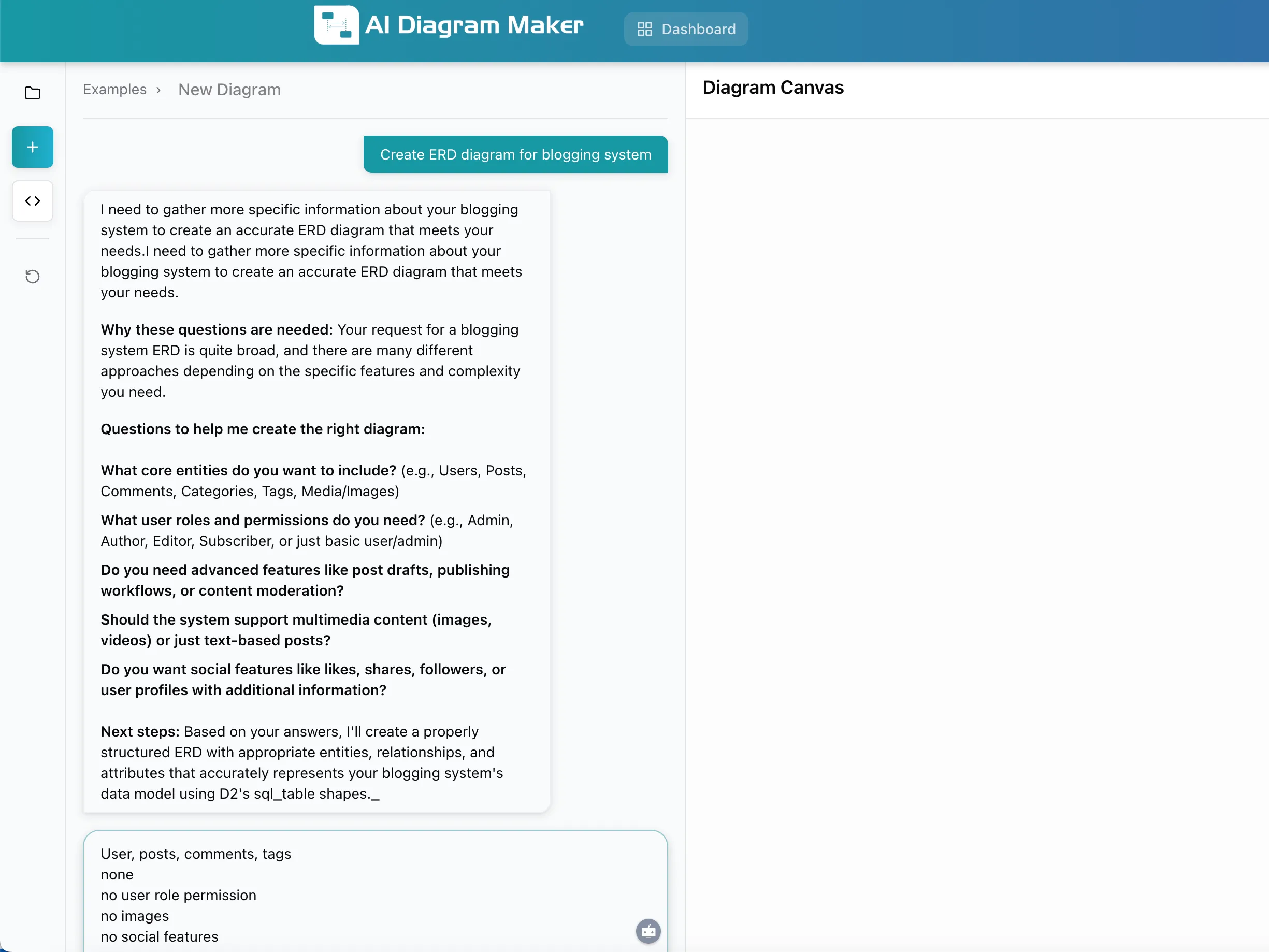
In this example, the user simply requested “Create ERD diagram for blogging system.” The AI recognized this was too broad and responded with targeted questions:
- What core entities should be included?
- What user roles and permissions are needed?
- Are advanced features like drafts or workflows required?
- Should multimedia content be supported?
- Are social features needed?
After the user provided simple answers (Users, posts, comments, tags / none / no user role permission / no images / no social features), the AI generated a complete ERD:
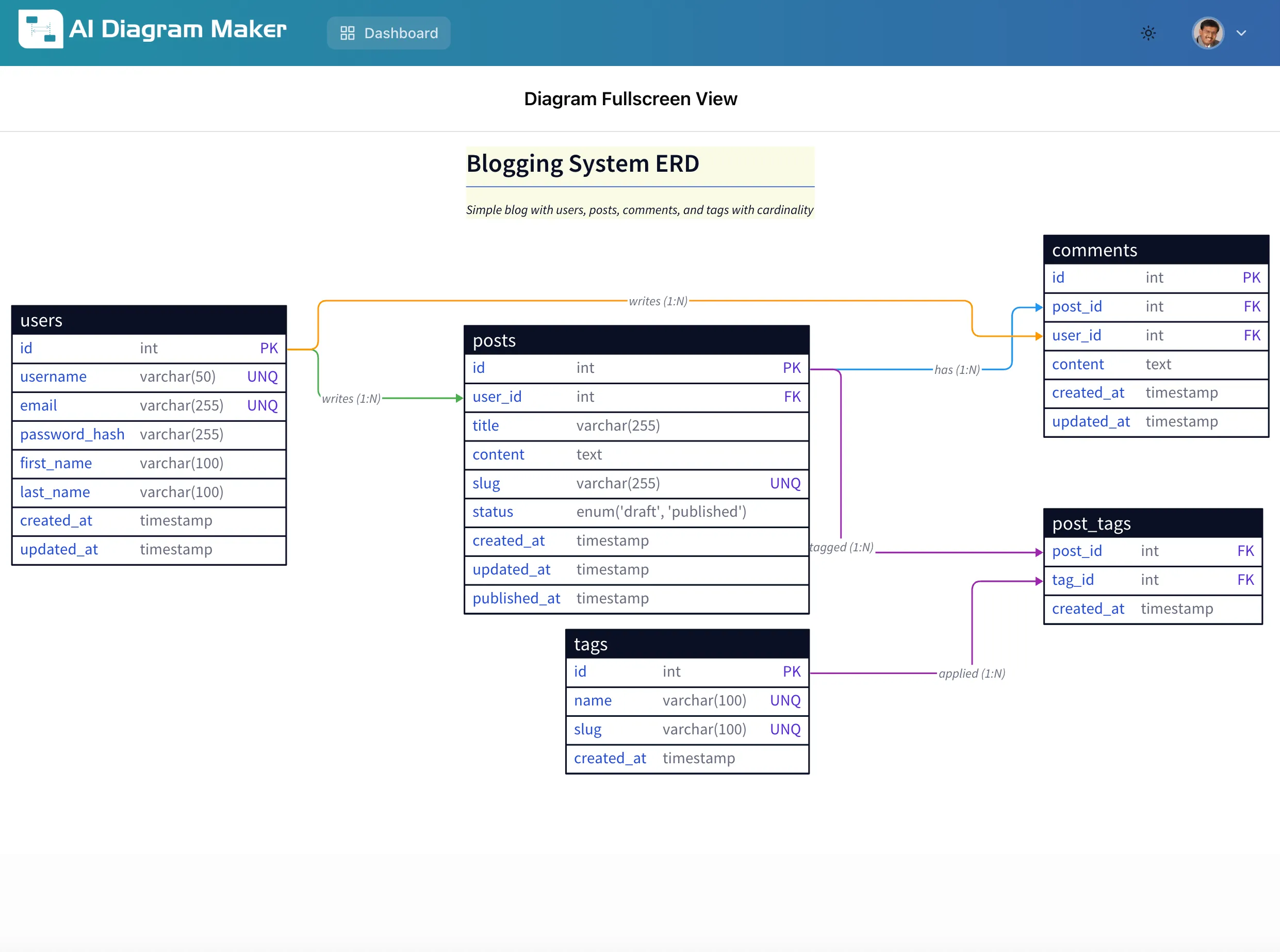
Result: A professional ERD with four entities (users, posts, comments, tags) and a junction table (post_tags) for the many-to-many relationship. The diagram includes:
- Proper primary keys (PK) and foreign keys (FK)
- Appropriate data types (int, varchar, text, timestamp, enum)
- Unique constraints (UNQ) on username, email, and slug fields
- Relationship cardinality labels (1:N for one-to-many)
- Clean, readable layout with all entities properly positioned
This interactive approach is ideal when you’re exploring design options and want AI guidance on best practices.
Example 2: Detailed Specifications to ERD
When you already know exactly what you need, you can provide complete specifications upfront and get an immediate diagram.
Input: Comprehensive requirements with entities, attributes, and relationships defined
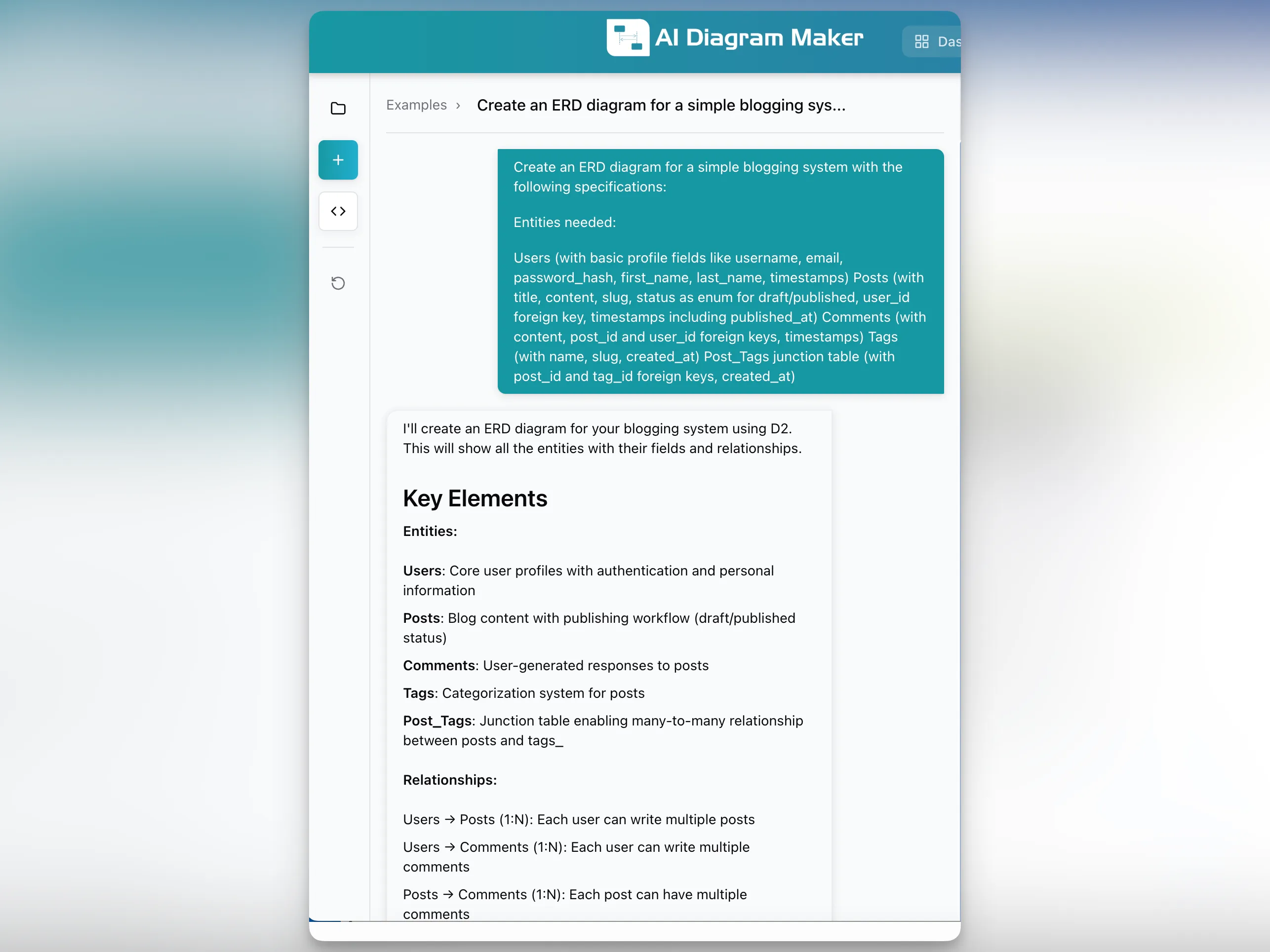
The user provided a detailed specification including:
Entities needed:
- Users (with basic profile fields like username, email, password_hash, first_name, last_name, timestamps)
- Posts (with title, content, slug, status as enum for draft/published, user_id foreign key, timestamps including published_at)
- Comments (with content, post_id and user_id foreign keys, timestamps)
- Tags (with name, slug, created_at)
- Post_Tags junction table (with post_id and tag_id foreign keys, created_at)
The AI analyzed this structured input and immediately generated:
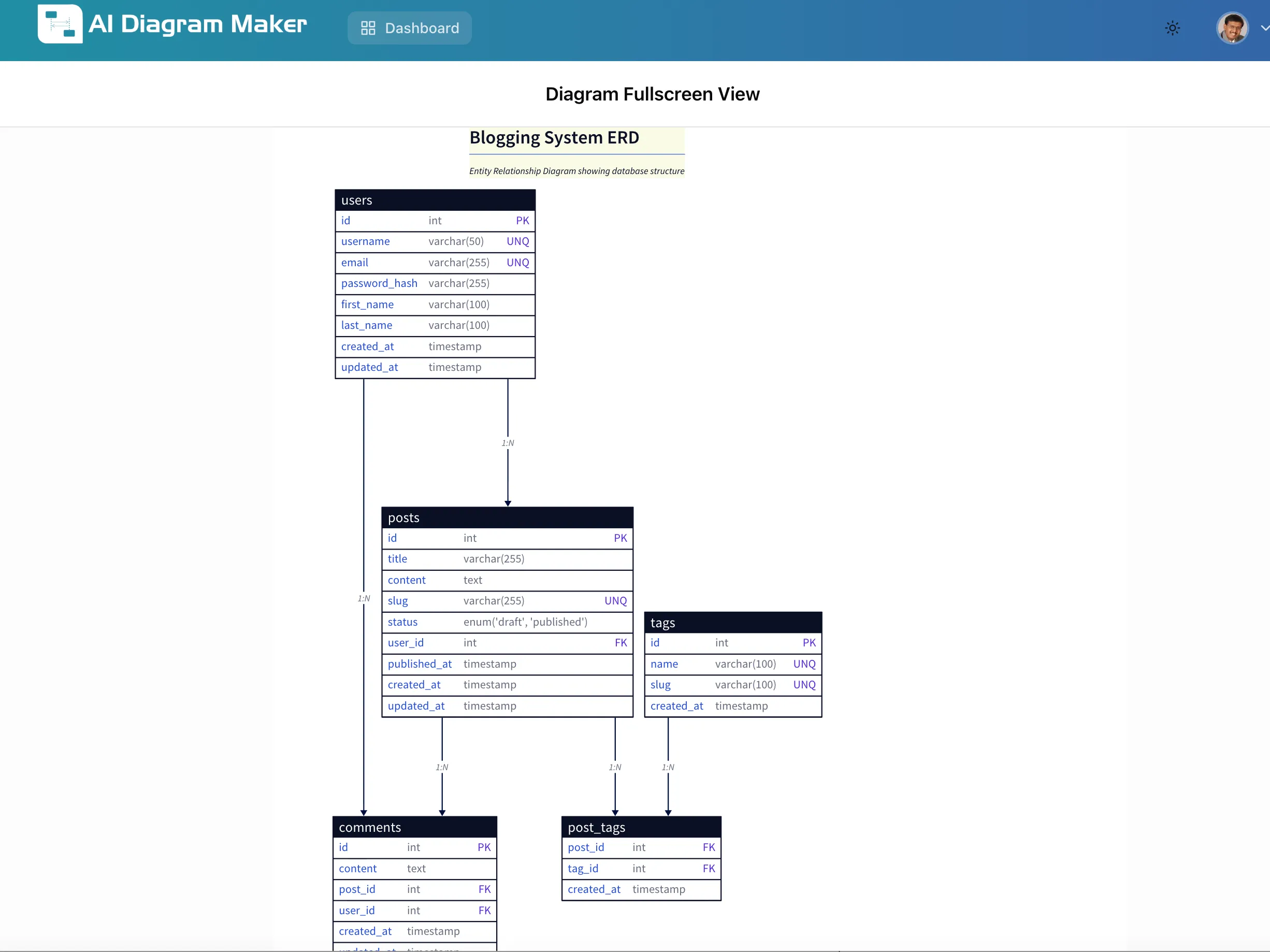
Result: A complete entity relationship diagram that accurately represents all specified requirements. The AI correctly:
- Created all five entities with proper table structures
- Implemented the many-to-many relationship using a junction table
- Added appropriate constraints (primary keys, foreign keys, unique constraints)
- Used proper data types for each field
- Organized the layout for optimal readability with clear relationship lines
This approach is perfect when you’ve already planned your database structure and just need quick visualization.
Example 3: Reverse Engineering SQL to ERD (Code to Diagram)
One of the most powerful features of AI ERD diagram generators is the ability to reverse engineer existing database schemas. This “code to diagram” workflow ensures your documentation stays synchronized with your actual database structure.
Input: PostgreSQL CREATE TABLE statements with foreign key constraints
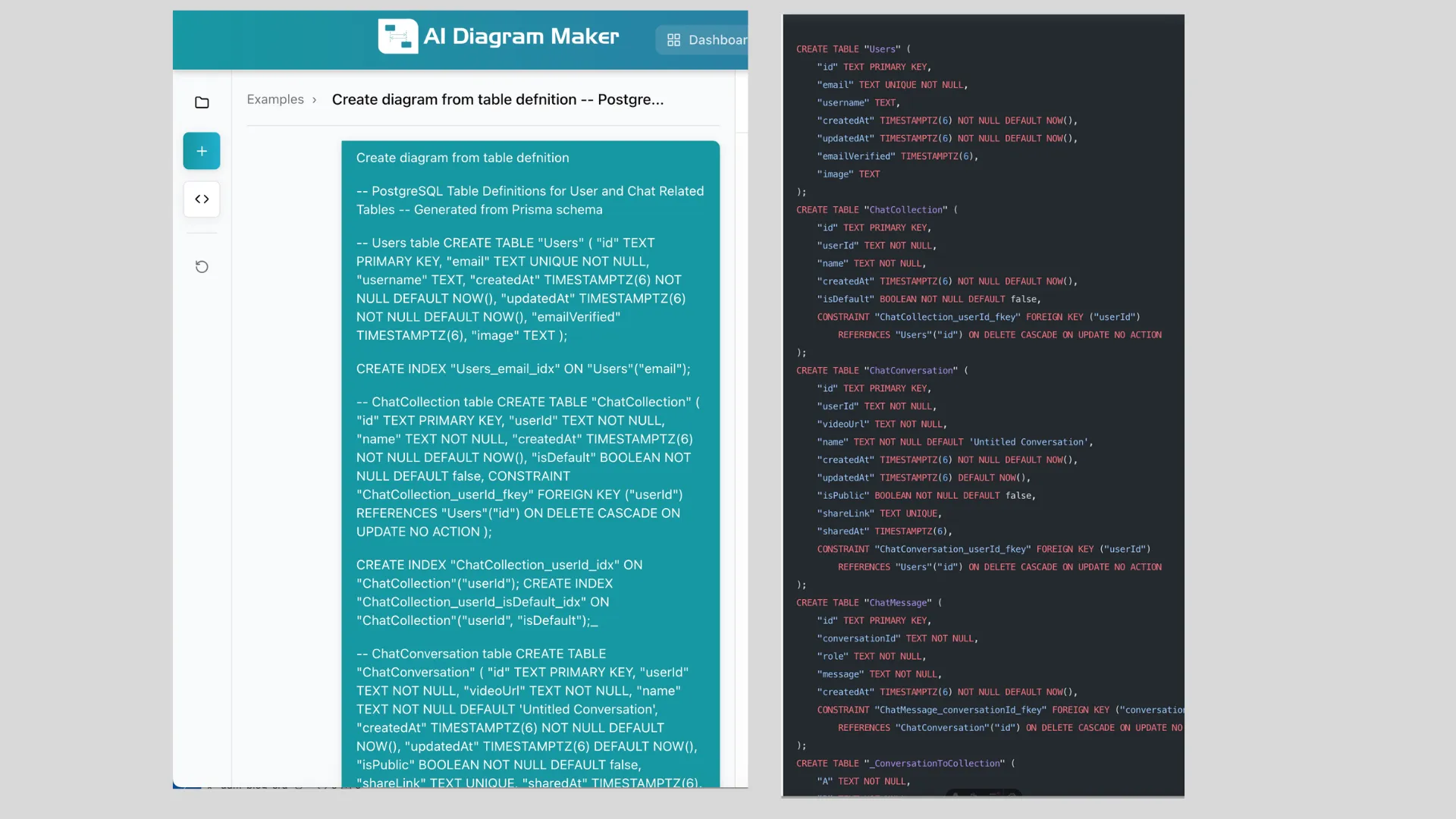
The user provided complete SQL schema definitions for a chat application, including:
-- Users table
CREATE TABLE "Users" (
  "id" TEXT PRIMARY KEY,
  "email" TEXT UNIQUE NOT NULL,
  "username" TEXT,
  "createdAt" TIMESTAMPTZ(6) NOT NULL DEFAULT NOW(),
  "updatedAt" TIMESTAMPTZ(6) NOT NULL DEFAULT NOW(),
  "emailVerified" TIMESTAMPTZ(6),
  "image" TEXT
);

-- ChatCollection table with foreign key to Users
CREATE TABLE "ChatCollection" (
  "id" TEXT PRIMARY KEY,
  "userId" TEXT NOT NULL,
  "name" TEXT NOT NULL,
  "createdAt" TIMESTAMPTZ(6) NOT NULL DEFAULT NOW(),
  -- Foreign key constraint
  CONSTRAINT "ChatCollection_userId_fkey" FOREIGN KEY ("userId")
    REFERENCES "Users"("id") ON DELETE CASCADE ON UPDATE NO ACTION
);

-- Additional tables: ChatConversation, ConversationToCollection, ChatMessage
The AI parsed the SQL code, extracted all table definitions, identified foreign key relationships, and generated:
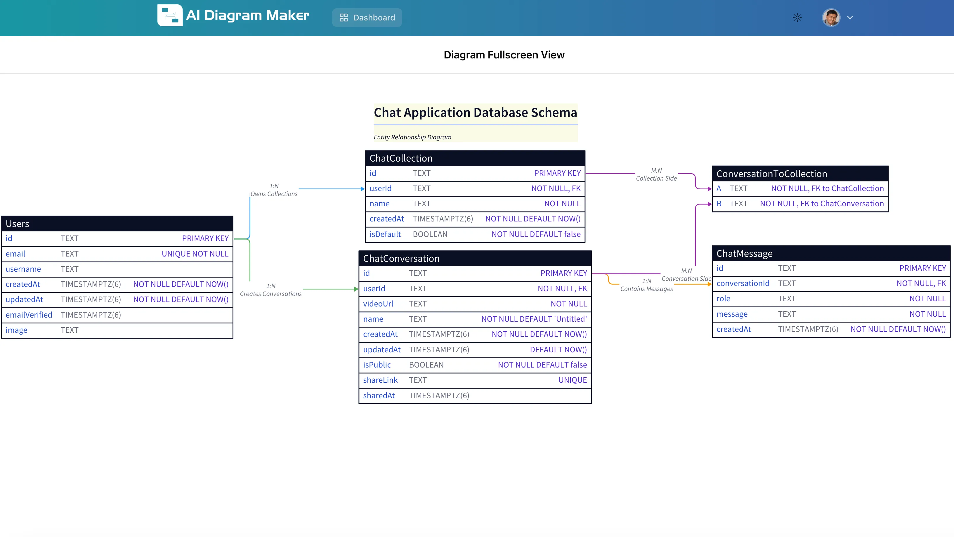
Result: An accurate ERD that perfectly represents the database schema with:
- All five entities (Users, ChatCollection, ChatConversation, ConversationToCollection, ChatMessage)
- Correct primary keys and foreign keys extracted from CONSTRAINT definitions
- Proper relationship lines showing one-to-many connections
- Data types and constraints (NOT NULL, UNIQUE, DEFAULT values) clearly displayed
- Junction table (ConversationToCollection) for the many-to-many relationship between conversations and collections
Why Code to Diagram Matters:
- Documentation sync: Automatically update diagrams when schema changes
- Legacy system understanding: Quickly visualize complex existing databases
- Database migrations: See the impact of schema changes before applying them
- Team onboarding: Generate current ERD diagrams from production schemas
- Code reviews: Visualize database changes in pull requests
This reverse engineering capability is essential for maintaining accurate documentation throughout the development lifecycle.
Example 4: Whiteboard Sketch to Professional ERD
Design discussions often start with rough sketches on whiteboards or in notebooks. AI ERD diagram generators can transform these informal drawings into professional diagrams without requiring any text description.
For a detailed walkthrough of converting a hand-drawn database schema sketch into a professional ERD, see our comprehensive guide: Converting Whiteboard Sketches to Digital Diagrams.
This example demonstrates how AI vision models can:
- Interpret messy handwriting and informal notation
- Recognize entities, attributes, and relationships from sketches
- Generate clean, professional ERD diagrams with proper formatting
- Apply database design best practices automatically
This image-to-diagram capability bridges the gap between ideation and documentation, eliminating the tedious manual redrawing step that typically follows design meetings.
Step-by-Step: Using an AI ERD Diagram Generator
1. Choose Your Input Method
Decide which approach fits your workflow:
- High-level prompt: Let AI ask questions to refine requirements
- Detailed specifications: Provide complete entity and relationship definitions
- SQL code: Upload or paste existing schema for reverse engineering
- Image upload: Take a photo of whiteboard or notebook sketches
2. Generate Your ERD
- Go to AIDiagramMaker
- Select “Create new diagram”
- Provide your input (text, code, or image)
- AI analyzes and generates the ERD in 30-60 seconds
3. Review and Refine
The initial output typically captures 90%+ of your requirements. You can:
- Ask AI to add missing entities or attributes
- Adjust relationships or cardinality
- Request specific formatting or layout changes
- Export to various formats (PNG, SVG, diagram-as-code)
Best Practices for AI ERD Generation
For Text-Based Input
- Be specific about relationships: Clearly state “one-to-many” or “many-to-many”
- Include data types: Mention if fields are integers, text, timestamps, etc.
- Specify constraints: Note unique fields, required fields, and foreign keys
- Use consistent terminology: Stick to standard database terms
For SQL Code Input
- Include foreign key constraints: These define relationships in the diagram
- Use clear table and column names: Improves diagram readability
- Add comments: SQL comments help AI understand intent
- Provide complete schema: Include all related tables for accurate relationship mapping
For Image Input
- Good lighting: Ensure text is legible in the photo
- Clear handwriting: Print letters work better than cursive
- Label relationships: Add arrows or lines between related entities
- Capture entire diagram: Don’t cut off parts of the sketch
Comparison: Manual vs. AI ERD Creation
| Aspect | Manual ERD Tools | AI ERD Generator |
|---|---|---|
| Time Investment | 1-3 hours per diagram | 30-60 seconds |
| Skill Requirement | Database design + diagramming | Basic requirements description |
| Reverse Engineering | Manual inspection + drawing | Automatic from SQL code |
| Sketch Conversion | Manual redrawing | Automatic from image |
| Updates | Manual edits | Regenerate from updated code |
| Consistency | Varies by creator | Standardized notation |
Conclusion
AI ERD diagram generators transform database documentation from a time-consuming chore into a quick, automated process. Whether you’re:
- Designing new databases: Start with high-level ideas and let AI guide you through design decisions
- Documenting existing systems: Reverse engineer SQL schemas to ERD diagrams automatically
- Converting sketches: Transform whiteboard discussions into professional diagrams
- Maintaining documentation: Keep diagrams synchronized with code changes
The code to diagram workflow is particularly valuable for teams that want documentation to reflect actual database structure without manual maintenance overhead.
For developers, database architects, and technical teams, AI entity relationship diagram generators eliminate the friction between database design and documentation, ensuring diagrams stay current and useful throughout the development lifecycle.
FAQ
What is an AI ERD diagram generator?
An AI ERD diagram generator is a tool that uses artificial intelligence to automatically create Entity Relationship Diagrams from various inputs like text descriptions, SQL code, or images. It eliminates manual drawing by understanding database structure and relationships.
Can I generate ERD from existing SQL code?
Yes, AI ERD generators can reverse engineer SQL schemas into diagrams. Simply paste your CREATE TABLE statements with foreign key constraints, and the AI will generate an accurate ERD showing all entities, attributes, and relationships.
What input formats are supported?
Most AI ERD diagram generators support:
- Text descriptions (high-level or detailed)
- SQL code (CREATE TABLE statements)
- Images (whiteboard photos, notebook sketches)
- Natural language prompts
How accurate are AI-generated ERD diagrams?
Accuracy depends on input quality. Well-structured SQL code produces 95%+ accurate diagrams. Text descriptions work best when you specify entities, attributes, and relationships clearly. Image inputs require legible handwriting and clear relationship indicators.
Can I edit the generated diagrams?
Yes, you can refine diagrams by providing additional instructions to the AI or by exporting to traditional diagramming tools. Most AI ERD generators allow iterative refinement through natural language commands.
How does this compare to traditional ERD tools?
AI ERD generators are significantly faster (seconds vs. hours) and don’t require manual drawing. They excel at reverse engineering and sketch conversion. Traditional tools offer more granular control but require more time and diagramming expertise.